To Optical information technology department
1. The optical scheme of hyperspectral hardware unit (HSU) COMIS of Korean microsatellite STSAT3 was reproduced.
According to the publications, Korean HSU weighs about 5 kg, and for the spectral range of 400–1050 nm ensures the generation of hyperspectral images with a spatial resolution of 30 meters (orbit altitude of 700 km) and a spectral resolution of 2–15 nm. Due to its record-breaking weight and size characteristics, this HSU was chosen as the basic prototype, which subsequently will be compared to the solutions being developed within the project.
Based on the publications, the optical system of the Korean HSU has been reproduced (Fig. 1). The Korean HSU includes a catadioptric lens and an Offner imaging spectrometer. As the dispersing element of the spectrometer, two prisms with complex curved surfaces are used. For performance validation, the optical system was analysed via the Zemax program for modelling optical systems.
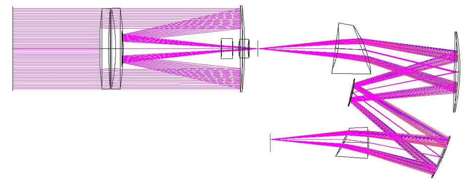
Figure 1. The optical scheme of the hyperspectral unit COMIS of Korean microsatellite STSAT3
The modelling results confirmed the high technical specifications of the Korean HSU. It was found that the optical system is close to the diffraction-limited one with the wavelength range of 400–1100 nm. Besides, the modulation transfer function value at the frequency level corresponding to the resolution of 30 meters is greater than 0.6 (Fig. 2). The spectral resolution of the system varies between 2 nm at a wavelength of 400 nm and 15 nm at a wavelength of 1050 nm. The above estimation of the spectral resolution was obtained for a pixel of the recording CCD with a size of 13 microns. The Zemax program also helped study the influence of errors in positioning of the scheme elements, element manufacturing errors and thermal strains on the size of the circle of confusion and the modulation transfer function value. The results showed the system tolerance to linear positioning errors of several microns and angular positioning errors of a few tenths of an arc minute.

Figure 2. The modulation transfer function of COMIS at a wavelength of 750 nm. Resolution of 30 m corresponds to the spatial frequency of 39 lpm.
As a disadvantage of the Korean HSU, we should note the high non-linearity of changing position of an image pixel when changing the wavelength. This drawback is caused by chromatic aberrations of prisms used as dispersive elements of the spectrometer. According to the project team, this disadvantage can be eliminated in the spectrometer using a diffraction grating formed on one of the mirrors as the dispersing element. This approach will significantly expand the recorded spectral range and improve spectral and spatial resolution of the system.
2. The software calculating multilayer structures consisting of continuous layers with plane boundaries (multilayer interference coatings) has been developed.
The software is based on numerically stable method using the scattering matrix (S-matrix) and implemented in the MATLAB development environment. The implemented method efficiently calculates the spectral filters containing both dielectric and absorbing isotropic and anisotropic materials. Modelling of light passing through the structure is made taking into account the optically thick incoherent layers, which allows to properly consider the influence of the finite thickness of the substrate coated with a multilayer coating (spectral filter). Using the developed software, the so-called linearly varying filters were calculated. The operating wavelength of the filter is changed in the direction of one dimension of its substrate surface. Linearly varying filters are based on using Bragg gratings with a defect, which are two symmetrical Bragg gratings separated by a defect layer with a specified thickness. The transmission spectrum of such a structure contains a narrow transmission peak located in the photonic bandgap of a Bragg grating and caused by excitation of a quasi-waveguide mode located in the defective layer. The position of the transmission peak is determined by the thickness of the defect layer, the width of the peak transmission (filter bandwidth) is defined by the number of periods in the Bragg gratings, the photonic bandgap (operating range of the filter wavelength) is characterised by the materials of the Bragg grating.
For the calculated and investigated at this stage examples of linearly varying filters, the width of the operating range is of 200–300 nm (filters were calculated for wavelengths of 500–700 nm and 700–1000 nm), filter bandwidth is of the order of 10 nm (bandwidth is a function of the operating filter wavelength and varies in the range 5–20 nm for these examples). For creating an HSU filter operating in a wide range of wavelengths, the calculated linearly varying narrowband filters must be used along with broadband filters reflecting light having wavelengths that are beyond the bandgap of the Bragg gratings used. Due to this, there were calculated broadband filters that transmit light in the range corresponding to the operating range of linearly varying filters. The calculated filters are multilayer structures made of the same materials as the linearly varying filters. The layer thickness of broadband filters has been obtained by the optimisation procedure. For example, Fig. 3 and 4 shows linearly varying narrowband filter for the wavelength range 500–700 nm, and the corresponding broadband filter.


Figure 3. Geometry of a linearly varying filter in the wavelength range of 500–700 nm (dielectric permittivity of the materials coloured and indicated in the legend, the thickness of the layers of the Bragg gratings comprise 95 and 59 nm) (a), the transmission spectrum of the defective Bragg grating for various thicknesses of the defective layer (indicated in the legend in nm) as a function of wavelength in nm (b)


Figure 4. Geometry of a broadband filter in the wavelength range of 500–700 nm (dielectric permittivity of the materials coloured and indicated in the legend, the thickness of the layers from the upper to the lower is 98, 39, 173, 80, 138, 85, 144, 72, 165, 57, 173, 62, and 84 nm) (a), the filter transmission spectrum function of wavelength in nm (b)
It has been shown that composite filters performing narrowband spectral filtering in the wavelength range of 500–1000 nm can be obtained by direct combination of the calculated broadband and linearly varying filters. The proposed approach can be used to create composite spectral filters operating in a wider spectral range.
3. The software for solving direct and inverse problems of the computation of multilayer metaldielectric nanostructures composed of continuous layers with periodic profile has been developed.
The direct problem involves modelling the diffraction of light on a structure, the inverse problem is calculating (obtaining the geometric parameters) a structure based on the specified criterion optimisation. The software implemented in MATLAB is based on two common methods of modelling electromagnetic diffraction on periodic structures: the Fourier modal method and the C-method. The Fourier modal method is optimal for modelling structures whose layers have a piecewise linear profile with segments parallel to the coordinate axes (square wave structures). The C-method is aimed at the modelling diffractive structures with a continuous (sinusoidal) profile. For multilayer structure modelling, the numerically stable advanced algorithm based on the transmission matrix is used. Using the developed software, diffractive structures consisting of 1–3 square wave and sinusoidal layers were calculated and studied. It has been shown that spectral filters with operating wavelength width of 300–400 nm (visible range is considered) and bandwidth of 20–100 nm can be created based on such structures. The structures of this type can be manufactured by sputtering continuous metal and dielectric layers on a sinusoidal or rectangular profile in the resist disposed on the substrate and constructed by interference or electron-beam lithography.